Moisture separator
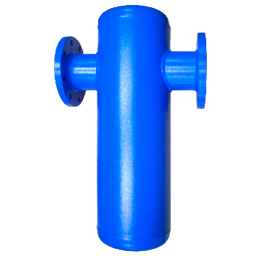
The moisture-laden air from the after cooler enters the separator; it is forced through a diffuser that spins the air around the separator's body. Droplets of water are made to impinge on the separator wall by centrifugal force and they get collected at the base of the separator by gravity.
Specifications
| Product Name | Moisture separator |
| Brand | Ganeshfilter |
| Operating pressure range | 4 to 8 bar |
| design operating pressure range | 12 bar @ 125°C |
| Design Code | ASME Sec VIII DIV I |
| Available capacity | 382, 552, 1105, 1750, 2250, 3950, 5400, 5825, 8525, 10775, 12550 M3/Hr |
| Inlet / outlet sizes | 1", 1 1/2", 2", 3", 4", 6",8", 10", 12",14", |
| Inlet & outlet connections | BSP(F),NPT(F) and Flanged to ANSI B 16.5 - #150 |
| drain & vent connections | 3/8", 1/2",1", |
| Material | Carbon Steel or 1.4301 quality 304 stainless steel |
| Avilable colour | Std Grey,optional Blue,Red |
| Usage/Application: | It is widely used in ◼Rotary Screw Compressors ◼Piston Compressors ◼Centrifugal Air Compressors ◼Paper Mills ◼Flare Stacks ◼Gas Pipelines ◼Oil Refineries ◼Air Conditioning ◼Soil Vapor Extraction ◼Petrochemical ◼Refrigeration Systems ◼Compressor Systems ◼Geothermal Power Plants ◼Combined Cycle Power Plants ◼Natural Gas Processing ◼Air or Steam Line Moisture Separator |
Air cooled Aftercooler
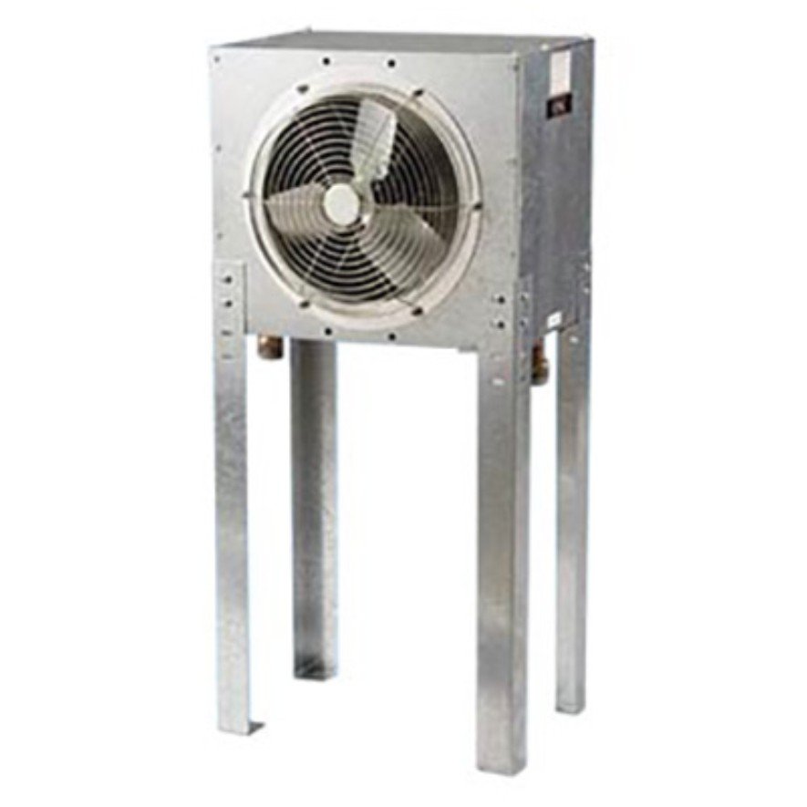
Air cooled After Coolers are of fine-tube construction with the compressed air passing through the tube. Air Cooled After Cooler transfer the heat from the compressed air to the atmosphere. The compressed air is cooled using a cooler fan. Air Cooled After Coolers are preferred because it is easy to install and no additional pipe lines for water and easy to maintain.
Specifications
| MODEL | Air Flow | In/Out | Dimensions in mm | Watts | Weight | |||
|---|---|---|---|---|---|---|---|---|
| M3/Hr | End Conn | A | B | C | D | Kg | ||
| GAC60 | 60 | 1" | 620 | 290 | 850 | 430 | 45 | 20 |
| GAC120 | 120 | 1" | 620 | 290 | 850 | 430 | 45 | 22 |
| GAC180 | 180 | 1 1/2" | 850 | 290 | 1025 | 475 | 110 | 29 |
| GAC240 | 240 | 1 1/2" | 1075 | 350 | 1025 | 575 | 130 | 34 |
| GAC300 | 300 | 2" | 1075 | 350 | 1025 | 575 | 130 | 52 |
| GAC390 | 390 | 2" | 1075 | 380 | 1025 | 575 | 700 | 53 |
| GAC480 | 480 | 2" | 1075 | 400 | 1275 | 575 | 700 | 56 |
| GAC720 | 720 | 2" | 1075 | 675 | 1525 | 575 | 750 | 95 |
| GAC960 | 960 | 2 1/2" | 1075 | 675 | 1525 | 575 | 750 | 125 |
| GAC1200 | 1200 | NB 75 | 1475 | 510 | 2025 | 660 | 650 | 245 |
| GAC1500 | 1500 | NB 75 | 1475 | 510 | 2025 | 660 | 650 | 255 |
| GAC1800 | 1800 | NB 100 | 1950 | 510 | 1975 | 850 | 650 | 288 |
| GAC2400 | 2400 | NB 100 | 2260 | 510 | 1975 | 850 | 2 x 750 | 310 |
| GAC3000 | 3000 | NB 125 | 3275 | 580 | 1875 | 880 | 2 x 1325 | 325 |
| GAC3900 | 3900 | NB 125 | 3275 | 590 | 1875 | 880 | 2 x 1325 | 370 |
| GAC4500 | 4500 | NB 150 | 3380 | 600 | 1875 | 925 | 2 x 1325 | 395 |
| Technical Details | ||||||||
| Operating Conditions | ||||||||
| Air Inlet temperature | 120 ℃ | |||||||
| Inlet Pressure | 7 bar(g) | |||||||
| Air outlet Temperature | 25 ℃,above ambient | |||||||
| Inlet Relative humidity | 70% | |||||||
| Max working Pressure | 16 bar(g) upto 25 bar available on request. | |||||||
| Inlet/Outlet connection | BSP / NPT / Flanged to ANSI B 16.5 | |||||||
| Drain Connection | BSP(F) Optional NPTF | |||||||
| Drain Type | Manual drain,( Optional - No loss Drain ) | |||||||
| STANDARD VOLTAGE | ||||||||
| Model BAC60 to 120 | 230V/1ph/50-60Hz | |||||||
| Model BAC60 to 120 | 400V/3ph/50Hz | |||||||
| Usage/Application: | ◼Rotary Screw Compressors◼Piston Compressors◼Centrifugal Air Compressors◼Vacuum Systems◼Blower Lube Oil Coolers◼Compressed Air Cooling. | |||||||


Water Cooled aftercooler
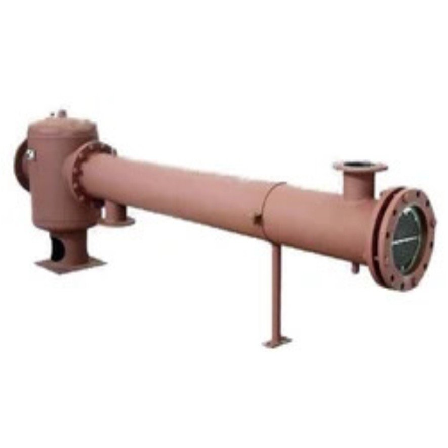
Water cooled After cooler is a Shell and Tube type Heat Exchanger which reduces the temperature of compressed Air and as a result Moisture from the Compressed Air is Separated. Cooling is done by circulating water from the opposite side of the Compressed Air inlet in Aftercooler.
Specifications
| MODEL | Air Flow | End Conn | Dimensions in mm | Water | Weight | |||
|---|---|---|---|---|---|---|---|---|
| M3/Hr | IN | OUT | A | B | C | IN/OUT | Kg | |
| GWC100 | 180 | 1 1/2" | 1 1/2" | 1150 | 40 | 395 | 1/2" | 20 |
| GWC200 | 360 | 2 1/2" | 1 1/2" | 1375 | 40 | 395 | 1/2" | 27 |
| GWC300 | 480 | 2 1/2" | 1 1/2" | 1575 | 40 | 395 | 3/4" | 29 |
| GWC400 | 850 | 100NB | 100NB | 1875 | 70 | 725 | 1" | 34 |
| GWC500 | 1500 | 100NB | 100NB | 1875 | 70 | 725 | 1" | 52 |
| GWC600 | 2400 | 150NB | 125NB | 2100 | 70 | 725 | 1 1/4" | 93 |
| GWC700 | 3000 | 200NB | 125NB | 2150 | 240 | 775 | 1 1/4" | 148 |
| GWC800 | 4800 | 250NB | 150NB | 2050 | 275 | 850 | 1 1/4" | 235 |
| GWC900 | 6600 | 250NB | 150NB | 2050 | 275 | 1525 | 1 1/2" | 290 |
| GWC1000 | 9000 | 300NB | 200NB | 2200 | 350 | 950 | 2" | 420 |
| GWC1100 | 10800 | 350NB | 200NB | 2400 | 350 | 950 | 2" | 490 |
| GWC1200 | 12600 | 400NB | 200NB | 2600 | 350 | 950 | 2 1/2" | 540 |
| Operating Conditions | ||||||||
| Ambient temperature | 35 DegC min. | |||||||
| Working pressure | 7 bar | |||||||
| Inlet air temperature (max) | BWC100-300 : 120 ℃ | |||||||
| BWC400-1200 : 200℃ | ||||||||
| Cooling Water | ||||||||
| IN-OUT water temperature | 15-25 ℃ | |||||||
| Water side pressure | 3 bar (7 max.) | |||||||
| Inlet/Outlet connection | BSP / NPT / Flanged to ANSI B 16.5 | |||||||
| Drain Connection | BSP(F) Optional NPTF | |||||||
| Drain Type | Manual drain,( Optional - No loss Drain ) | |||||||
| Usage/Application: | ◼Rotary Screw Compressors ◼Piston Compressors ◼ Centrifugal Air Compressors ◼ Vacuum Systems ◼ Blower Lube Oil Coolers ◼ Compressed Air Cooling ◼ Oil Coolers ◼Hydraulics ◼Approach/Trim Coolers | |||||||

